- Lg colour tv circuit diagram
- Videocon Tv Circuit Diagram - Circuit Diagram Images
- Colour tv circuit diagrammes
- Colour tv Circuit Diagram | CIRCUIT DIAGRAMS FREE
- China colour tv kit circuit diagram
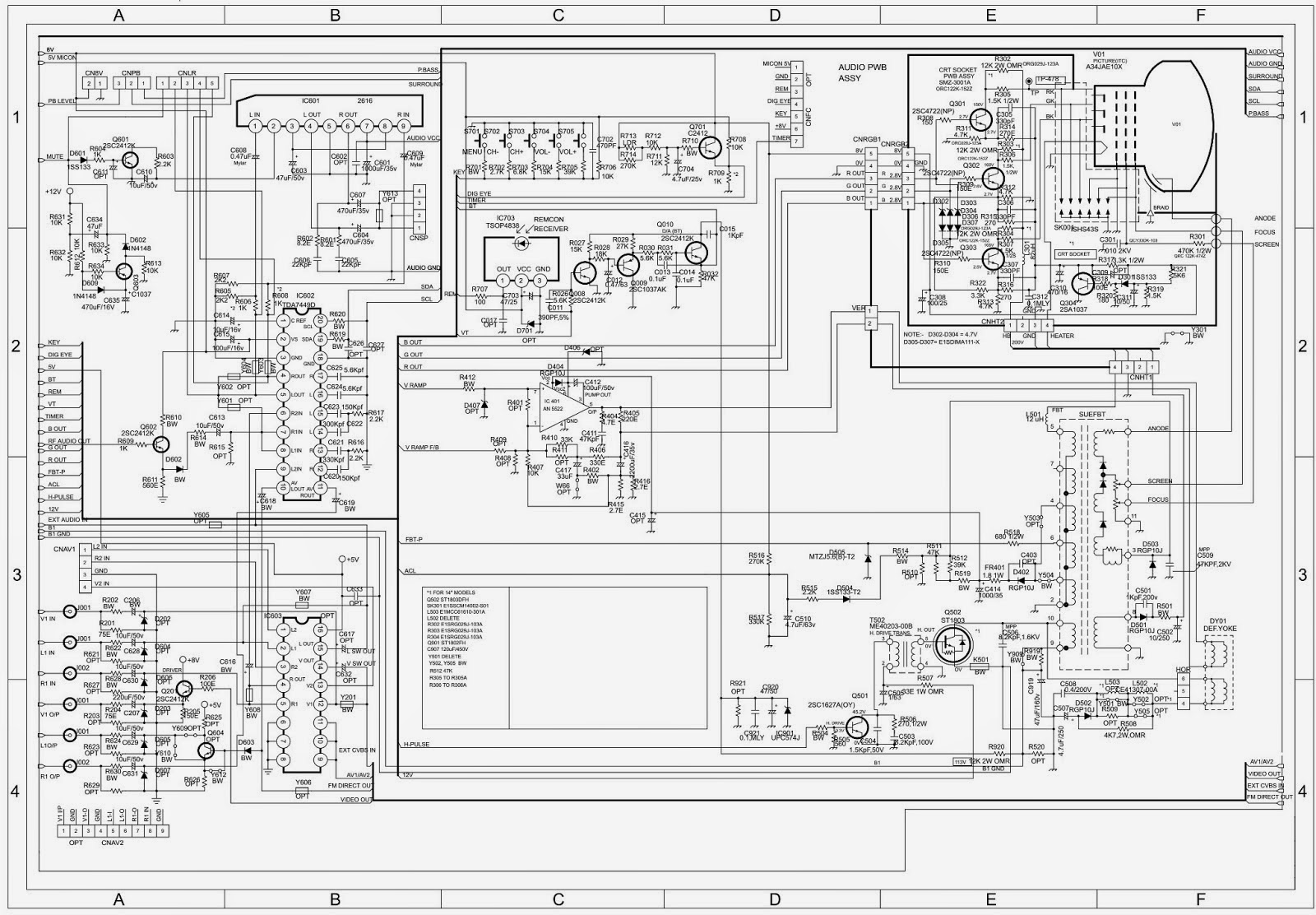
Schematic diagram of switching power supply for color television, which can used on a particular color TV, how it works using the switching transformer and switching transistors. At first voltage AC220V entry through the capacitor and resistor, and then immediately rectified AC voltage by 4 diodes and capacitor given on each diode. After a DC voltage then passes through a capacitor elco in parallel, and into the circuit and the voltage is lowered by the switching transformer. After the voltage is lowered and then was rectified and filtered again in the after circuit, the output voltage is set up on their own. For output +5V and +12V using ic stabilization 7805 and 7812. To use circuit switching power supply can be used on the same output voltage. If the circuit is working you should never ever touch the live area, because of the high-voltage section. And if the circuit has stopped working, do not forget to remove the voltage on the capacitor electrolyte, by linking the two legs to the lamp or solder.
Lg colour tv circuit diagram
Videocon Tv Circuit Diagram - Circuit Diagram Images
TDA9341
– AT24C08 - CD4052 – AN7522 – TDA2003 – [LOT
BSC25-N0832/BSC25-T1010A/BSC24-01N4014K] – Transistorized SMPS
FBT variations: FOR 29"
BSC26-01-N4010F BSC26-N2143
BSC26-01N4010E BSC26-N2148
BSC26-01N4004F BSC26-01N
REPLACEMENT OF MEMORY IC
This TV circuit uses memory IC. In the memory IC are memorized data for correctly operating the video and deflection circuits. When replacing memory IC, be sure to use IC written with the initial value of data. PROCEDURE FOR REPLACING MEMORY IC
(1) Power off
Switch the power off and unplug the power cord from AC outlet. (2) Replace IC
Be sure to use memory IC written with the initial data values. (3) Power On
Plug the power cord into the AC outlet and switch the power On. (4) Check and set system default value:
1) Press " MENU " key followed by digits ' 6''4''8 ' and '3'. Then Press "TEST" key on the Remote control unit for factory used. 2) The red "M"or"factory" will be displayed on the screen, repeat this and it will changed as follow:
normal-M(factory)-BUS open-normal..
3) Press digital key, (Mkey) and corresponding on-screen display will be appeared.
Colour tv circuit diagrammes
After the voltage is completely lost, the circuit is already safe and avoid danger.
- Paw fiction
- Color tv circuit diagram
- COLOUR TV CIRCUIT DIAGRAM - Auto Electrical Wiring Diagram
- Sharon Cullen | Historical Romance and Paranormal Romance Author
- Schematic Diagrams: Color TV circuit diagram using TDA9341 IC 14 and 21 inch – Service mode - Memory IC replacement
- El puente de terabithia
- Cancionero catolico salesiano pdf
- Colour tv circuit diagram pdf
Colour tv Circuit Diagram | CIRCUIT DIAGRAMS FREE
RCA
introduced the CT-100 a few weeks later, at a price of $1000 (about 4000 were made). GE sold its 15 inch set for $1, 000, Sylvania's cost $1, 150. Emerson
rented color sets for $200 for the first month and $75/month thereafter. By the summer of 1954 there was already a shakeout. A headline in the
New York Times said "Set Buying Lags - Public Seen Awaiting
Larger Screens, Lower Prices". Motorola and CBS promised a 19
inch screen at $995. In 1955, Raytheon introduced a 21 inch set for $795 and CBS offered a
trade-in of up to $400 for their black and white sets towards the
purchase of a $895 21 inch color model. By the end of 1957 only 150, 000 color sets had been sold. Color
sales were slow until the mid 1960s, when the reliability of sets
improved, prices came down, and more color programming became available. Read these Time
Magazine articles from 1956 and 1958. In the late 60s color sets became more reliable and cheaper, and more network TV shows were televised in color, so color sales accelerated.
wireless video transmitter | Electronic Circuit Diagram and Layout Mini Wireless Video Transmitter Circuit Diagrams, DIY The wireless video, audio signal sender circuit, vhf wireless video transmitter, wireless video transmitter, WIRELESS TRANSMISSION, portable micro transmitter provides high quality stable video transmission..... in this small black enclosure Learn electronics for beginners with easy ways | How to Learn electronics for beginners, students, who Interested in the hobby. Or parents who want to find good activities for children. DIY Location Tracker using GSM SIM800 and Arduino This GSM car tracker system project will use GPRS of SIM800 GSM module which will be connected with a microcontroller like Arduino. Over Voltage, Over Current, Transient Voltage & Reverse Polarity Protection Circuit using RT1720 Hot Swap Controller with Fault Timer In this tutorial we design, calculate, and test an over voltage, over current, transient voltage and reverse polarity protection circuit using RT1720 IC.
China colour tv kit circuit diagram
>better quality signal from your antenna would prevent the loss of color. All TV`s have a "color killer" circuit, designed to turn off the color circuits when the signal goes B/W, so you don`t get the "beat pattern" of the color subcarrier on top of the monochrome video. > make it sure that you have not messed up with your remote settings
>>Turn off your tv and unplug your video cable from the source and from the tv. Replug it, see if that helps. Sometimes the cables get loose. >this is most likely going to be a problem in the box. > just check with the different cables attached with your tv and cable or dish top box.. check the following cables if they are attached properly and not loose
Component cables
Composite cables:
HDMI: 1 wire between the tv and the device, this is a single wire and looks like a computer plug on each end, similar to a large USB connector. Coax: This is 1 wire between the tv and the device as well. This is the normal cable wire with the end the screws.

2 pin case smd semicondutor components. Vision electronic for repairing tv technics and fault finding new electronic gadgetsand many more for electronics. Epanorama software and tools section. The rgb color model is an additive color model in which red green and blue light are added together in various ways to reproduce a broad array of colors. View and download sony icf cd555tv service manual online. Icf cd555tv lcd tv pdf manual download.
- Pan chaplains